

_500x500.jpg)
『Flow Meter and Control Valve Installation Guidelines: Proper Spacing to Prevent Cavitation』Related information(v cone flow meter|rotary gas meter|gallon meter|gear meter|metal tube rotameter|glass tube rotameter|nutating disk meter|transit time ultrasonic flow meter|wedge flow meter|pd meters|hydraulic flow meter|ultrasonic water flow meter|water flow meter|air flow meter|magnetic water flow meter|oxygen flow meter|gas flow meter|argon flow meter|air velocity meter|gasoline flow meter|fuel flow meter|ultrasonic water meter|digital water meter|nitrogen flow meter|solid flow meter|Oxygen tank flow meter|digital water flow meter|diesel fuel flow meter|steam flow meter|02 flow meter|compressed air flow meter|oil flow meter|liquid flow meter)
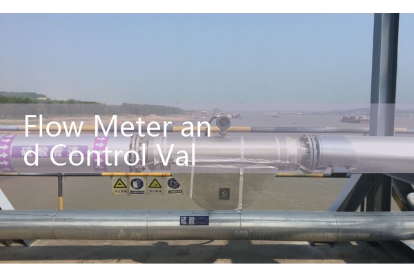
Flow Meter and Control Valve Installation Guidelines: Proper Spacing to Prevent Cavitation
Quick Answer: Flow meter and control valve spacing controls accuracy and service life. Place the flow meter upstream of the control valve whenever possible. If the meter must sit downstream, keep at least 10D to 20D of straight pipe between the valve outlet and the sensor.
Why Spacing Between a Flow Meter and a Control Valve Matters
Control valves throttle flow and create high velocity jets. A control valve that drops pressure can turn liquid into vapor bubbles. This is cavitation. The bubbles collapse downstream and produce shock waves. These shock waves damage meter liners, electrodes, ultrasonic transducers, and vortex shedder bars. A flow meter installed too close to a control valve sees unstable flow, two phase conditions, and false readings.
Most engineers skip this part. They focus on sensor selection and forget that pipe hydraulics decide how the meter performs. We have seen this on customer sites many times.
Where to Place the Flow Meter Relative to the Control Valve
The best location is upstream of the control valve. Upstream flow is usually more stable and single phase. A control valve downstream does not disturb the meter inlet profile if enough straight run exists before the meter. The upstream straight run still depends on the fitting before the meter. For an electromagnetic flow meter, keep at least 5D upstream and 3D downstream. For a vortex flow meter, use 15D upstream and 5D downstream after a partial valve. For an ultrasonic flow meter, keep 10D upstream and 5D downstream. For a Coriolis mass flow meter, straight run is less critical but cavitation and aeration still shift density readings.
If the meter must go downstream of the control valve, add more straight pipe. A reduced bore or high pressure drop valve produces a jet that needs distance to mix and settle. In practice, 10D is a starting point. For high pressure drops above 5 bar, use 20D or more. A flow conditioner can help but adds pressure loss and cost. We have seen customer sites where 10D was not enough for a DN100 vortex meter after a control valve. The meter showed a 3 percent reading swing until we moved it upstream.
How Cavitation Damages Flow Meter Sensors
Cavitation forms when local pressure drops below the vapor pressure of the liquid. The control valve throat is the common zone. Bubbles move downstream and collapse when pressure recovers. The collapse point is often near the meter body. The repeated shock loads cause pitting on metal surfaces. Electromagnetic flow meter liners can crack. Ultrasonic transducers lose acoustic coupling. Vortex shedder bars erode. Oval gear flow meters can jam if vapor bubbles lock the gears.
A paint manufacturer in Southeast Asia installed a DN80 electromagnetic flow meter only 4D after a control valve. The reading fluctuated by 8 percent. The liner showed pitting after five months. We moved the meter upstream of the valve and the reading stabilized to under 0.5 percent. That is the difference spacing makes.
Recommended Minimum Straight Runs After a Control Valve
Use these values as a starting point for liquid lines.
DN15 to DN50: keep 15D of straight pipe after the valve outlet.
DN65 to DN150: keep 20D of straight pipe after the valve outlet.
DN200 to DN300: keep 25D
For slurries, high viscosity fluids above 100 cP, or gas-liquid mixed flows, increase the distance by 50 percent.
These numbers assume the valve outlet pressure is above the liquid vapor pressure. If not, no spacing will fix the accuracy problem.
Pressure and Backpressure Rules That Prevent Cavitation
Do not rely on spacing alone. Backpressure is just as important. Keep the pressure downstream of the control valve at least 1.5 times the vapor pressure of the liquid at the operating temperature. For water at 80 °C, the vapor pressure is about 0.47 bar absolute. The downstream pressure should stay above 0.7 bar absolute to reduce cavitation risk. For a hydrocarbon or solvent, check the vapor pressure curve. A pressure transmitter with 4-20 mA HART output can monitor this backpressure. Add a PT100 temperature sensor because vapor pressure changes with temperature.
For high pressure drops, use a multi-stage trim valve or an anti-cavitation valve. This reduces the pressure in steps and prevents the local pressure from falling too low. In oil and gas areas classified as ATEX Zone 1, the flow meter and pressure transmitter should have the proper hazardous area certification.
Data to Send Us for a Spacing Check
Send us your pressure (bar), temperature (°C), pipe size (DN), and flow range. Also include the valve type, valve size, and the straight pipe length available. We will check the cavitation risk and recommend a meter location. Contact Silver Automation Instruments at +86-25-68650347. WhatsApp is +86-25-52155837. WeChat is +86 15365082610. You can also visit flow-meter.com.au for product details. For clean water in a DN80 line, ask us for an electromagnetic flow meter with PTFE liner and 4-20 mA HART output. For chemical batches or fuels, ask us for a Coriolis mass flow meter or an oval gear flow meter rated for your viscosity.
FAQ
How far should a flow meter be from a control valve? Place the meter upstream of the valve if possible. If the meter is downstream, use at least 10D to 20D of straight pipe between the valve outlet and the sensor. High pressure drops need longer runs.
Can a flow meter be installed downstream of a control valve? Yes, but cavitation and turbulence become bigger risks. Keep backpressure above 1.5 times vapor pressure. Add straight run or a flow conditioner. A Coriolis mass flow meter tolerates flow profile distortion better but still errors under two phase flow.
What flow meter type handles cavitation best? No flow meter works well under cavitation. A Coriolis mass flow meter can handle some density shifts but loses accuracy with gas bubbles. An electromagnetic flow meter can work if the liner survives. A vortex flow meter will show unstable signals. Fix the installation first.
How do I know if cavitation is affecting my flow meter? Look for unstable readings, pitting on the sensor, noise, or liner damage. If the meter is just downstream of a control valve and the reading moves more than expected, cavitation is a likely cause.
What data does Silver Instruments need to recommend spacing? Send pressure (bar), temperature (°C), pipe size (DN), flow range, valve type, and available straight run. We will reply with a meter location and model suggestion.
 Hot Product
 Related AD