

 Current position > News detail
『Ultrasonic Flow Meter Transducer: Clamping and Acoustic Gel Installation Rules』Related information(v cone flow meter|rotary gas meter|gallon meter|gear meter|metal tube rotameter|glass tube rotameter|nutating disk meter|transit time ultrasonic flow meter|wedge flow meter|pd meters|hydraulic flow meter|ultrasonic water flow meter|water flow meter|air flow meter|magnetic water flow meter|oxygen flow meter|gas flow meter|argon flow meter|air velocity meter|gasoline flow meter|fuel flow meter|ultrasonic water meter|digital water meter|nitrogen flow meter|solid flow meter|Oxygen tank flow meter|digital water flow meter|diesel fuel flow meter|steam flow meter|02 flow meter|compressed air flow meter|oil flow meter|liquid flow meter)
Ultrasonic Flow Meter Transducer: Clamping and Acoustic Gel Installation Rules
Quick Answer
Quick Answer: A clamp-on ultrasonic flow meter transducer install needs a clean rust-free pipe surface, correct spacing set by the flow meter, stable clamping pressure, and a thin continuous layer of acoustic couplant. Most errors come from thick paint, dry gel, loose straps, or mounting too close to a pump or elbow. Silver Instruments supplies clamp-on ultrasonic flow meters for pipe sizes from DN15 to DN6000 with standard and high temperature transducer options.
Surface Preparation Before Clamping
Before you clamp the transducer, remove paint, rust, scale, and loose coating from the pipe surface. A hand wire brush is not enough on old carbon steel lines. Use a 100 mm flap disc or angle grinder to expose bright metal over a strip at least 60 mm wide and 200 mm long. We have seen a fish processing plant in Vietnam lose signal on a DN100 brine line because a 0.5 mm epoxy paint layer absorbed the acoustic pulse. After light grinding, the signal strength returned from below 200 to above 600 on the Silver Instruments display.
Clean the prepared area with a degreaser or alcohol. Let it dry fully. Do not use water as the final cleaner on hot pipes because evaporation can cool the surface and create a thin condensation layer. Measure the actual wall thickness with an ultrasonic thickness gauge. The flow meter needs the outer diameter, wall thickness, pipe material, liner type and thickness, fluid type, and fluid temperature. If you skip the thickness gauge and only use the nominal pipe schedule, the mounting distance can be off by a few millimetres. On a DN50 carbon steel line, that small error can drop the signal by half.
Acoustic Couplant Application Rules
Apply the acoustic gel or grease directly to the centre of the transducer face. Spread it with the transducer itself or a plastic spatula. A layer of 1 mm to 2 mm works for most pipe surfaces from DN20 to DN300. Too thin a layer leaves air gaps. Too thick a layer adds a variable acoustic path. The flow meter reading may jump when the pump starts or when the pipe warms up. Most engineers skip this part, but couplant thickness is a common cause of unstable flow rates on small pipes.
Use standard silicone couplant for surface temperatures from minus 30°C to 120°C. Use high temperature acoustic couplant for pipes above 120°C up to 200°C. Do not use general purpose ultrasound gel used for medical probes. It dries fast on hot metal and attacks some plastics. On vertical pipes apply a slightly thicker layer at the top edge so gravity does not pull the gel away before you clamp. Reapply couplant every time you move the transducer. Clean the old gel off with a dry cloth or plastic scraper first. Dried gel on a transducer face acts like an acoustic barrier.
Clamping Force and Strap Rules
The strap or clamp must hold the transducer tight enough to prevent sliding, but not so tight that the plastic wedge deforms. For small transducers used on DN15 to DN80 pipes, a clamping force from 50 N to 100 N is usually enough. For larger transducers on DN100 to DN6000 pipes, use 150 N to 300 N. If you can move the transducer by hand after tightening, the force is too low. If the transducer face shows a concave mark after removal, the force was too high.
Use stainless steel straps for outdoor, marine, or wastewater installations. Nylon straps can stretch in sun and rain. Magnetic clamps are fine for temporary surveys on carbon steel but do not use them on plastic or stainless steel pipe unless you add a bracket. Check the mounting after the first 24 hours on hot water or thermal oil lines. Thermal expansion can loosen a strap by a few millimetres. A water utility in Malaysia found this on a DN250 chilled water line. The flow meter worked during commissioning and lost signal the next morning because the strap settled.
Mounting Path and Transducer Spacing
Let the flow meter calculate the spacing. Do not copy a spacing value from one project to another. The value changes with pipe material, wall thickness, liner, fluid sound speed, and transducer frequency. For a clean water DN50 carbon steel pipe with a 2 MHz transducer, the space between the transducer front edges is often around 42 mm. On a DN100 cement lined ductile iron pipe, the spacing can be two or three times that. Enter the parameters into th
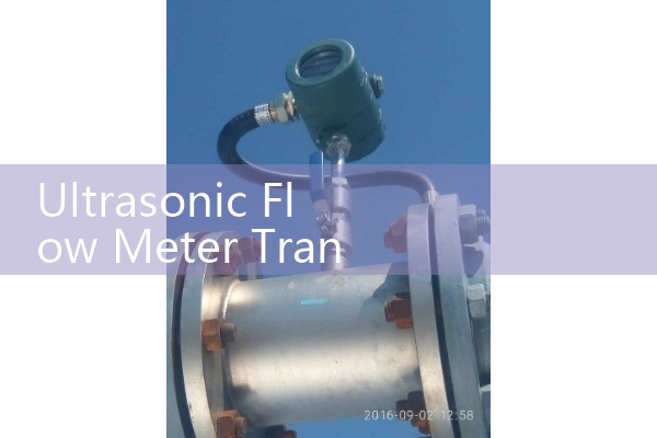
Choose V-path mounting for small pipes from DN15 to DN100. Choose Z-path mounting for larger pipes or weak signal conditions from DN80 to DN6000. W-path is mainly used for very small pipes from DN10 to DN50 with low flow velocity. Mount the transducers on the side of a horizontal pipe at the 3 o clock and 9 o clock positions. Side mounting prevents gas bubbles at the top or sediment at the bottom from blocking the signal. On vertical pipes you can mount at any angle, but the flow should move upward so bubbles travel in the same direction.
Signal Check and Quick Troubleshooting
After clamping, check the signal quality on the flow meter. On Silver Instruments clamp-on ultrasonic flow meters, a signal value above 500 or a signal to noise ratio above 20 dB usually gives a stable reading. The flow range should stay within 0.1 m/s to 12 m/s. If the signal is low, shift one transducer by 5 mm forward or back along the pipe and watch the value. Do not move both transducers at once. Add a small amount of fresh couplant if the signal jumps while you press on the transducer. That usually means the strap is loose or the couplant layer has gaps.
Keep the transducer cables away from variable frequency drives and large motors. Use shielded cable and route it at least 300 mm from power cables. If the flow meter reading drops when a nearby pump starts, the problem is often electrical noise or air in the liquid. Add 1 bar to 2 bar back pressure on wastewater and slurry lines to suppress free gas. An ink factory in Thailand replaced a faulty flow meter before checking the transducer cable. The actual fault was a damaged cable shield near a mixer motor.
Recommended Silver Instruments Clamp-On Models
Silver Instruments supplies wall mount and portable clamp-on ultrasonic flow meters for clean water, wastewater, chilled water, hot water, and some hydrocarbon liquids. The SUP-1158 series wall mount clamp-on ultrasonic flow meter takes standard transducers for DN20 to DN100 and high temperature transducers for pipes up to 200°C. For field checks and pump audits, the portable clamp-on ultrasonic flow meter works from DN15 to DN6000. Both units accept pipe outer diameter, wall thickness, and fluid type to compute the correct transducer spacing automatically.
A typical wall mount clamp-on ultrasonic flow meter from Silver Instruments has an accuracy of plus or minus 1.0 percent of reading for pipes DN50 and above after a proper install. It outputs 4-20 mA, pulse, RS485 Modbus, and can run on 24 VDC or 220 VAC. For a temporary flow survey on a DN200 cooling water line, we normally supply a portable unit with a carrying case, stainless steel straps, a tube of silicone couplant, and a 20 metre transducer cable pair.
FAQ: Transducer Clamping and Acoustic Gel Installation
Can I reuse acoustic couplant after removing a transducer? No. Clean the old layer off and apply fresh couplant. Old couplant collects dirt and air pockets.
How much acoustic gel should I apply? Use a 1 mm to 2 mm continuous layer on the transducer face. Enough to fill small surface gaps, not enough to squeeze out around the entire strap.
Do I need special couplant for hot water pipes? Yes. Use high temperature couplant above 120°C. Standard silicone gel dries and cracks on hot metal.
Why does the signal drop after some months? Couplant drying, strap loosening, or surface corrosion are the usual causes. Check these three before replacing the transducer.
Can I install clamp-on transducers on old pipes with heavy rust? You can, but only after grinding to bright metal. If the wall is too thin or pitted, choose a different location or use a spool piece with a flow meter.
Get a Firm Quote for Your Pipe and Fluid
Send us your pipe size (DN), pipe material, wall thickness, flow range, fluid type, and temperature. We will recommend the correct transducer, clamping method, and couplant type. Contact Silver Automation Instruments: Tel: +86-25-68650347. WhatsApp: +86-25-52155837. WeChat: +86 15365082610. We supply clamp-on ultrasonic flow meters to water plants, food processors, marine engineers, and chemical users in Southeast Asia, Oceania, Latin America, the Middle East, and Africa. Data sheets are available at flow-meter.com.au.